Learning objectives
By the end of this topic the learner will be able to:
- Describe the operating principles of traditional (mechanical) and modern electronic ignition systems.
- Identify common faults in ignition systems and the symptoms they produce.
- Perform basic, safe diagnostic tests using simple, low-cost tools commonly available in resource‑constrained African contexts.
- Apply practical repair and preventive strategies using local materials and low-cost methods where appropriate.
1. Overview — purpose and basic function
The ignition system’s purpose in a gasoline engine is to create a timed, high‑voltage spark at each cylinder’s spark plug to ignite the air–fuel mixture. Correct timing, consistent spark energy, good electrical connections and a reliable control signal (from distributor, crank/cam sensors or ECU) are essential for engine starting, smooth running, fuel economy and low emissions.
Two broad families:
- Traditional mechanical ignition: battery → ignition coil → distributor (points or electronic pickup) → spark plug wires → spark plug.
- Modern electronic ignition (including coil‑packs and coil‑on‑plug): includes sensors (crank/cam), ignition modules and an Engine Control Unit (ECU) or dedicated ignition control, which switch coils electronically for more precise timing and reliability.
2. Components and how they work (concise)
- Battery and charging system: provide reliable voltage for coil primary circuit.
- Ignition switch, fuses, relays: supply and protect ignition circuits.
- Ignition coil: steps up 12 V to thousands of volts. Two windings: primary (low ohms) and secondary (kΩ).
- Distributor (if present): mechanical rotor/cap directs high voltage; may contain contact breaker points or electronic pickup (magneto/reluctor or Hall sensor).
- Points and condenser (old systems): mechanical timing and suppression of arcing across points.
- Ignition module / transistor: electronic switching of coil primary current in many systems.
- Crankshaft/camshaft sensors: provide position reference for timing to the ECU.
- Engine Control Unit (ECU): calculates when to fire coils (and other functions).
- Spark plugs and high-tension leads (HT leads): deliver the spark to the combustion chamber.
- Grounds and wiring: often the weakest link in poor environments.
3. Typical symptoms and probable causes
- Engine does not crank or cranks but does not start: check battery and fuel first. If fuel present, suspect no spark (coil, ECU, sensors, wiring, distributor).
- Intermittent starting or misfire at idle/high rpm: poor connections, cracked plug wires, weak coil, failing sensor, moisture/corrosion.
- Rough idle, loss of power, unstable timing: weak spark, incorrect timing, ECU sensor problems.
- Backfiring, pre‑ignition or pinging: incorrect timing, wrong spark advance, or mechanical faults.
- Visible arcing outside plug insulator or from faulty wires/cap: lead or cap failure.
4. Safety notes (must read before testing)
- High voltage hazard: ignition systems can produce several thousand volts. Avoid touching spark plugs, coil terminals or HT leads while engine is being cranked or running.
- Remove metal jewelry and gloves that could entangle.
- Work in a well‑ventilated area away from fuel vapour and open flames.
- Disconnect the battery negative terminal for certain tests or repairs where recommended.
- Use insulated tools when working near live circuits.
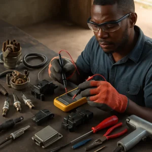
5. Low‑cost tools and supplies (recommended)
- Digital multimeter (basic DC/AC volts, resistance, diode test) — highest priority.
- 12 V test lamp (bulb + leads) — inexpensive for checking power and switches.
- Simple spark tester (in-line) or a steel spare spark plug and insulated lead as a crude tester (use with great caution).
- Feeler gauges for points and spark plug gap.
- Screwdrivers, pliers, wire cutters/strippers, adjustable spanner.
- Small wire brush, emery cloth, contact cleaner or degreaser (brake cleaner can be used carefully).
- Soldering iron and basic solder; heat shrink and insulating tape.
- Multimeter probes and alligator leads.
- Spare cap, rotor, spark plug wires and spark plugs (salvage from donor vehicles is often cheaper).
- Timing light (useful but optional; there are affordable models).
- Basic replacement fuses, crimp connectors, dielectric grease.
6. Diagnostic approach — step‑by‑step (resource‑aware)
Start with the simplest checks, proceed from battery toward the spark plug.
-
Visual inspection
- Check battery terminals, cable tightness and corrosion.
- Inspect ignition wires, cap, rotor, plug condition, and visible wiring/connectors for cracks, corrosion or loose connections.
- Look for oil or fuel contamination on distributor cap/plug insulators.
-
Battery and supply voltage
- Measure battery static voltage: ~12.6 V (fully charged). While cranking, voltage should not fall below ~9–10 V for a healthy battery.
- Use test lamp to confirm ignition feed at fuse/ignition switch.
-
Confirm presence of spark (safe method)
- Use a proper spark tester in the HT lead or an inline tester. If unavailable, remove a plug, reconnect to plug wire, hold the plug metal body against a clean metal part of the engine (insulated handle, not touching with hand), crank engine and visually inspect spark gap — only if you know the risks. Prefer a spark tester.
- If no spark, proceed to isolate primary/secondary circuit.
-
Check coil primary and secondary
- With ignition OFF and disconnected, measure coil primary resistance (across primary terminals). Typical values vary by coil: common ranges 0.4–3 Ω. Consult manual when available. Extremely high or infinite resistance = open coil.
- Measure coil secondary resistance (between high voltage terminal and primary negative). Typical thousands of ohms (kΩ). Again, ranges vary. Open or shorted = coil defective.
- If you lack exact spec, compare with known good coil or swap coil (if removable) with donor unit.
-
Distributor & points systems
- Inspect cap and rotor for carbon tracking, cracks and moisture. Clean or replace.
- Check and adjust points gap using feeler gauge (typical ~0.4–0.6 mm depending on engine). Check condenser by substitution if suspect.
- Clean rubbing block, cam and lubricate contact points appropriately.
-
Electronic pickup / sensor testing
- Reluctor (magnetic) sensor: with engine cranking, measure AC voltage between sensor leads — a small AC voltage should be present. Alternatively measure resistance; values vary widely — consult manual or swap with known good.
- Hall effect sensor: check for supply voltage (often 5 V or battery) with ignition ON, and an output pulsing between 0 and supply voltage when cranking. Use multimeter on DC setting or test lamp to see switching. If no switching, suspect sensor or wiring.
-
Ignition module / ECU
- Check fuses, power and ground at module/ECU connectors. Use test lamp or multimeter.
- Wiggle connector wiring while cranking to see if spark fails intermittently — poor connector or broken wire may be the cause.
- In many resource‑limited contexts, swapping with a known-good module from a donor vehicle (same type) is the practical test.
-
Coil packs and coil‑on‑plug (COP)
- Swap coil packs between cylinders to see if misfire or no‑spark follows coil.
- Inspect boots and seals; replace cracked boots.
- Check wiring to coil for proper supply voltage and control signal from ECU.
-
Final functional checks
- After repairs, verify spark at plugs, engine starts, idles smoothly and runs under load.
- Use a timing light to confirm ignition timing where required, and adjust to specification.
7. Common faults, root causes and low‑cost repair strategies
-
Symptom: No spark at all
- Possible causes: blown fuse, faulty ignition switch, dead battery, broken primary wiring, failed coil, bad ECU/ignition module, failed crank sensor.
- Low‑cost actions:
- Check and replace fuses; clean battery terminals.
- Use test lamp to trace ignition supply to coil/module.
- Swap coil or module with a known-good donor.
- Check and repair broken wires (solder and heat shrink whenever possible).
-
Symptom: Weak spark or misfires
- Possible causes: degraded coil, worn spark plugs, damaged HT lead or cap, poor earth/ground.
- Low‑cost actions:
- Replace spark plugs and cap, rotor; use salvaged good units from scrapyard if new parts costly.
- Clean contacts and apply dielectric grease to connectors.
- Improve ground by cleaning mounting surfaces and adding ground straps.
-
Symptom: Intermittent spark / no start when hot or vibrating
- Possible causes: heat‑sensitive ignition module, cracked coil, poor solder joints, intermittent connector.
- Low‑cost actions:
- Inspect for cracked coil housing — swap with donor to test.
- Reflow solder joints on ignition module connectors if competent and safe; otherwise replace.
- Secure connectors, clean and apply corrosion protection.
-
Symptom: Spark visible at plug but engine still misfires
- Possible causes: incorrect timing, weak fuel supply, compression loss.
- Low‑cost actions:
- Check timing with basic timing light; set static timing if necessary.
- Check compression if available (basic compression tester), or perform a cylinder wet/dry test using a small amount of oil in cylinder to identify low compression.
-
Symptom: Arcing/flashover from coil to body or between spark plug wires
- Possible causes: cracked insulation, degraded wires, oil/fuel contamination.
- Low‑cost actions:
- Replace wires/cap; if cost prohibitive, carefully clean and dry, insulate with high‑voltage resistant materials (commercial taped high voltage insulation is best — improvised insulation rarely reliable).
- Ensure distributor cap venting and keep cap dry.
Repair notes:
- Replace rather than repair high‑voltage parts (coils, cables) where possible. For long‑term reliability, scavenged good parts from donors are acceptable when new parts are unavailable.
- Avoid makeshift high‑voltage wiring unless you understand insulation needs; poor insulation creates intermittent faults and safety hazards.
- Use basic soldering for low‑voltage wiring and secure mechanical connections; use heat‑shrink, and avoid relying solely on ordinary tape.
8. Testing examples with simple tools
Example A — Confirming coil primary supply
- Tools: test lamp or voltmeter.
- Procedure:
- Turn ignition ON (engine OFF).
- Probe the coil primary positive terminal with test lamp or voltmeter; verify battery voltage present.
- If no voltage, trace back to fuse/ignition switch/relay.
Example B — Basic coil resistance check with multimeter
- Tools: multimeter.
- Procedure:
- Disconnect coil from circuit.
- Measure primary resistance across the two low‑voltage terminals (consult spec or compare with known good). Abnormally high or infinite = open primary.
- Measure secondary resistance between coil high‑tension terminal and one primary terminal; open or shorted readings indicate coil failure.
Example C — Checking a Hall or Hall‑effect pickup
- Tools: multimeter (DC volts).
- Procedure:
- With ignition ON, check sensor supply (often 5 V or battery voltage) at sensor connector.
- Crank engine and observe sensor output; it should switch between low and high voltage.
- No switching indicates faulty sensor, wiring, or missing reference.
Example D — Using spark tester (safe)
- Tools: inline spark tester.
- Procedure:
- Connect tester between coil output (or HT lead) and spark plug.
- Crank engine and check for consistent spark across tester gap.
- No spark: proceed with coil and module tests.
9. Preventive maintenance and good practices for resource‑limited workshops
- Regularly replace spark plugs at recommended intervals; a well‑gapped plug improves ignition reliability.
- Keep distributor cap, rotor and wires dry and clean. Store replacement caps/wires in clean, dry containers.
- Ensure good battery condition and secure ground connections; poor grounding causes many electrical gremlins.
- Use dielectric grease on connectors to prevent corrosion.
- Maintain a small stock of common consumables (plugs, cap, rotor, wires, fuses) and a donor vehicle/engine as parts source.
- Keep wiring loom protected from heat and chafing; repair insulation immediately if damaged.
- Record component measurements and faults for future reference (helps when using donor parts).
10. When to seek specialist help
- Suspect ECU faults beyond basic power/ground checks.
- Complex coil rewinds or internal coil repairs — these require specialized equipment and expertise.
- Intermittent high voltage arcing that cannot be traced to a simple cracked wire or cap.
- If safety risks are present (fuel leaks, severe electrical damage).
11. Practical exercises (recommended for learners)
- Visual inspection and cleaning: remove distributor cap, inspect, clean, and replace if necessary. Measure spark plug gaps and replace a spark plug.
- Coil testing: measure primary and secondary resistance of an ignition coil; record and compare with a reference unit.
- Sensor verification: measure crank sensor supply and output while cranking (with assistance); practice simple wiring continuity checks.
- Fault simulation: disconnect coil positive wire and confirm engine will not start; reconnect and confirm start. This reinforces circuit function.
12. Summary and key takeaways
- Reliable ignition requires good power supply, solid wiring/grounds, a competent coil and accurate timing information from sensors or mechanical timing.
- Many ignition faults can be found with basic tools: multimeter, test lamp and visual inspection.
- In resource‑constrained environments use careful inspection, substitution with known‑good donor parts, and basic repair skills (soldering, cleaning, connector repair).
- Prioritize safety: high voltage and fuel vapour risks demand careful procedures and the use of appropriate testers where available.
References and further study (suggested)
- Manufacturer repair manuals and wiring diagrams (essential where available).
- Basic electronics and multimeter use tutorials.
- Local vocational training centres and experienced mechanics for hands‑on guidance.
End of topic.