Learning objectives
By the end of this topic learners will be able to:
- Explain the principles of orthographic projection and the purpose of front, top and side views.
- Produce simple orthographic drawings of typical automotive components (engine parts, brake parts, etc.) using accepted projection conventions.
- Interpret and draw hidden detail lines correctly to show features not visible in a given view.
- Select and draw appropriate sectional views (full, half, offset, revolved, broken-out, removed) to reveal internal geometry required for repair or manufacture.
- Apply correct drawing conventions for cutting-plane lines, hatching, scales and basic dimensioning relevant to workshop practice.
- Use low-cost, locally available tools and methods to practice and communicate orthographic and sectional drawings in resource-constrained environments.
Why orthographic and sectional views matter in automotive work
Orthographic projection and sectional views are the universal language of engineering drawings. For technicians they:
- Communicate exact geometry needed for disassembly, inspection, repair, and manufacture.
- Eliminate guesswork about internal features (ports, oil galleries, recesses, cross‑bores).
- Help estimate fit, clearances and required tools or fixtures without access to the original CAD files.
- Are low-cost, robust documentation methods ideal for workshops with limited digital resources.
In low-resource contexts, clear orthographic and sectional drawings reduce time lost to trial-and-error repair and improve the safety of modifications.
Basic theory: Orthographic projection
- Orthographic projection represents a 3D object by two-dimensional views projected onto planes at right angles to each other.
- Common principal views: Front (elevation), Top (plan), and Side(s) (right and/or left). These three views are normally sufficient to fully describe a simple part.
- Projection methods:
- First-angle projection: object placed between observer and projection plane (common in Europe/Asia). Views are arranged differently (e.g., top view below front view).
- Third-angle projection: projection plane between observer and object (common in North America). Views are arranged in a different layout (top view above front view).
- Always state which projection method is used on the drawing (e.g., “Third-angle projection”) to avoid misinterpretation.
Practical note: For local teaching, pick one convention (commonly taught in your national standards or the workshop practice) and mark it clearly on each drawing.
Creating correct front/side/top views — method
- Orient the part in the most informative position for the front view: choose the face that shows the most important features.
- Establish the principal planes: vertical (front view), horizontal (top view), and side (right/left).
- Project feature outlines orthogonally (use perpendicular projection lines) from one view to the next.
- Maintain consistent scale for all principal views on the same drawing sheet.
- Use line-weights and types: visible edges (continuous thick), hidden edges (short dashed), centerlines (long-short-long thin), dimension lines (thin), cutting planes (thick dashed or thick thin with arrows).
- Check for completeness: every feature must be fully defined by the set of views (if not, include an additional view or sectional view).
Common errors to avoid:
- Misalignment of views (vertical and horizontal projection lines must match corresponding features).
- Omission of hidden lines when needed to show holes or recesses.
- Mixing projection conventions without labeling.
Hidden lines: representing unseen geometry
- Use short dashed lines for edges not visible in a particular view (e.g., internal holes, grooves).
- Do not overuse hidden lines; only show necessary hidden features to avoid clutter.
- Hidden lines should not be confused with centerlines; use centerlines for axes of holes, shafts and symmetric elements.
- In section views, do not show hidden lines for features revealed by the cut — show their true profile instead.
Practical tip: When teaching, have learners first draw visible outlines only, then add hidden lines as a second step to reinforce spatial understanding.
Sectional views: purpose and basic types
Sectional views show the interior of a component by slicing through it. They are essential when internal detail cannot be clearly communicated by hidden lines or additional orthographic views.
Common types:
- Full section: object is cut entirely along a plane; one half shows the interior.
- Half section: typically used for symmetric parts — one quadrant shows the interior while the other quadrant shows the exterior.
- Offset (or stepped) section: cutting plane bends to pass through important, non-collinear features.
- Revolved section: cross-section is rotated (revolved) onto the drawing beside the object and used for shafts, bars or spokes.
- Broken-out section: a small portion is removed to reveal interior without cutting the entire part.
- Removed (or detached) section: a section view drawn separate from the main view, aligned or repositioned for clarity.
Choosing the section:
- Use the simplest section that clearly shows all internal features needed for repair/manufacture.
- Prefer full sections for complex internal cavities; use half-sections for symmetric parts to show both interior and exterior.
- Use offset sections when holes or bores are offset from a single plane.
Drawing conventions for sectional views
- Cutting-plane line: draw as a thick dashed line with long dashes and arrowheads indicating viewing direction. Label the line with letters (e.g., A–A, B–B).
- Hatching (section lining): fill the cut surfaces with thin, evenly spaced parallel lines at about 45°.
- Maintain consistent spacing and angle across the drawing.
- Do not hatch over centerlines, dimension lines, or cutting plane lines.
- When two adjacent parts are sectioned, vary the hatch angle or spacing to distinguish materials.
- Indicate removed material only; do not hatch areas of empty spaces (e.g., holes) — instead show hole boundary.
- For symmetric revolved sections, show the sectioned profile beside the feature and line it up with the axis.
- Avoid unnecessary hatching for castings or complex assemblies; sometimes a single representative sectional view is preferred.
Material representation:
- Standard practice uses a uniform hatch for generic parts; specific material patterns exist for metals, rubber, etc., but beginners should focus on 45° hatch unless industry standards are required.
Procedure: producing a sectional view (step-by-step)
- Determine which view (front/top/side) best locates the cutting-plane for relevant internal features.
- Draw the principal view to scale, with visible and hidden lines as required.
- Sketch the cutting-plane line across the view; mark arrowheads showing the observer direction, and label the cutting plane (A–A).
- Project the outline for the sectional view using perpendicular projection lines.
- Replace all material on the cut face by hatching; show true profiles for features intersected by the plane.
- Remove hidden lines that are revealed by the section; only include hidden lines remaining in uncut areas.
- Add centerlines, dimensions, material notes and projection symbol (first/third angle).
- Check clarity: every feature required for repair/manufacture should be visible and measurable.
Reading sectional views: interpretation tips
- Follow the arrow direction of the cutting plane: you view the cut surface from that side.
- Areas hatched are solid material in the plane of the cut; clear areas with boundaries can be empty (holes) or separate components.
- For assemblies, sectioning conventionally shows the part of interest in section and leaves other parts unsectioned or hatched differently.
- For symmetric parts, half-sections show both interior and exterior detail; be cautious to associate hidden lines correctly on the un-sectioned half.
- Use centerlines to locate holes and axes; they remain visible even when sectioning.
Automotive examples and applied exercises
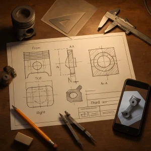
Example 1 — Piston and wrist pin:
- Task: Draw front, top and right-side views of a piston including hidden lines for wrist pin bore and oil gallery. Then produce a full section through the piston center to show skirt thickness and pin bore details.
- Key features to show: pin bore location, axis centerline, ring grooves, skirt thickness distribution. Use hatching in section and remove hidden lines for features exposed by the cut.
Example 2 — Connecting rod:
- Task: Orthographic views and a half-section through the big end to show bearing cap, bolt holes, and inner radius fillets.
- Key teaching outcome: recognition of symmetry, use of half-section to show interior and exterior.
Example 3 — Brake caliper or master cylinder (complex cavity):
- Task: Use offset or removed section planes to reveal internal bores and piston recesses. Label seals and mounting features.
- Key teaching outcome: demonstrate offset section to capture both piston bores and bolt features in one view.
Teaching exercise format:
- Provide a physical component or simple mock-up made from wood or clay.
- Measure with vernier caliper or ruler; sketch to scale on paper.
- Create orthographic views, then select an appropriate cutting plane and draw section.
- Annotate dimensions, material notes and projection method.
- Peer-review: swap drawings and interpret colleague’s sectional view to ensure understanding.
Low-cost tools and workshop techniques
- Tools: pencil, eraser, scale (ruler), protractor, set squares, compass, vernier caliper (priority), tape measure, tracing paper, graph paper.
- Making sections without cutting: build a cardboard model of the component and physically cut to study cross-section; use clay or wire to highlight cavities.
- Digital aids: smartphone camera to take orthogonal photographs; print photographs, overlay tracing paper and practice projecting views.
- For hatching practice: use consistent thin lead pencils (HB or 2H) and a parallel rule or straightedge.
- Materials list for resource-constrained contexts: scrap plywood for mock-ups, aluminum cans for thin-wall examples, clay for casting internal shapes, bicycle spokes for centerlines.
Common mistakes and how to correct them
- Misaligned views: use construction projection lines and check alignment frequently.
- Incorrect use of hidden lines: only show hidden lines necessary to describe a feature; remove hidden lines revealed by a section.
- Improper hatch application: keep direction and spacing consistent; do not hatch non-material zones.
- Unlabeled projection method: always add the projection symbol and label (First-angle or Third-angle).
- Missing scale or inconsistent scales: indicate scale on the drawing and use the same scale for related views.
Assessment criteria / Marking rubric (suggested)
- Correct choice and arrangement of principal views: 15%
- Accurate projection and alignment between views: 20%
- Correct representation of hidden lines where required: 10%
- Appropriateness and correctness of sectional view chosen: 20%
- Correct cutting-plane lines, hatching and section labeling: 15%
- Clear dimensioning and annotation (projection, scale, material): 10%
- Neatness, line quality and overall readability: 10%
Safety and ethical considerations
- When documenting repaired parts, ensure accuracy; incorrect drawings can lead to unsafe repairs.
- Respect intellectual property: do not reproduce proprietary designs without authorization.
Practice assignments (recommended)
- Measure and draw orthographic views and a full section of a simple cylindrical part (e.g., a small cylinder with a through-hole).
- Create orthographic views and a half-section of a connecting rod or a U-shaped bracket.
- Using a brake master cylinder or mock-up, draw an offset section that reveals both the piston bore and the inlet/outlet passages.
- Peer review: exchange drawings and write a short report identifying errors and suggested improvements.
Provide solutions or model answers in the next lesson or as downloadable templates showing each step and a correctly finished drawing for comparison.
Final pedagogical tips
- Begin with simple symmetrical parts; progress to assemblies and complex cavities.
- Encourage hand-drawing skills first — they build spatial understanding that transfers to CAD later.
- Use real components and low-cost mock-ups to connect drawing practice to workshop reality.
- Reinforce the habit of labeling projection method, scale and drawing title on every sheet.
End of topic.