This topic covers the practical use and maintenance of common flow and pressure measurement devices suitable for beginner technicians working in resource-constrained African contexts. Emphasis is on safe, robust, low-cost methods and locally available alternatives. Content includes principles, step-by-step measurement procedures, maintenance and troubleshooting, calibration methods, and practical design tips for simple devices (manometers, Venturi, orifice plates, Pitot tubes, floating indicators, and bucket-and-timer methods).
1. Principles and common relationships
-
Continuity (incompressible flow):
Q = A · V
where Q = volumetric flow rate (m^3/s), A = cross-sectional area (m^2), V = average velocity (m/s). -
Bernoulli (steady, incompressible, inviscid, along streamline):
p + 0.5·ρ·V^2 + ρ·g·z = constant
Differences in total and static pressure are used to infer velocity. -
Dynamic pressure (from Pitot-type measurement):
q = p_total − p_static = 0.5·ρ·V^2
=> V = sqrt(2·q/ρ) -
Hydrostatic (manometer) relation:
Δp = ρ_liquid · g · Δh
For differential columns using a single manometer liquid, the pressure difference between two points equals the product of manometer fluid density, gravity, and the vertical displacement between columns (taking into account fluid density differences when both fluids are present). -
Orifice and Venturi relations (simplified forms):
For an orifice: Q = C_d · A_o · sqrt(2·Δp/ρ)
For a Venturi: Q = C_v · A_t · sqrt(2·Δp/(ρ·(1 − (A_t/A_1)^2)))
where Cd or C_v are discharge coefficients (empirical), A_o or A_t are throat areas, A_1 is upstream pipe area, and Δp is the measured differential pressure between upstream and throat.
Notes:
- Coefficients depend on Reynolds number, pipe geometry, β ratio (β = d_throat/D_pipe), roughness and installation. Use empirical values from references or calibrate locally.
- Density (ρ) must be known (or measured) for fluids; temperature affects density and viscosity.
2. Common devices, use and low-cost alternatives
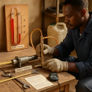
2.1 Manometers (U-tube, inclined, differential)
- Purpose: measure pressure or differential pressure using column heights of a liquid.
- Low-cost materials: clear PVC or acrylic tubing, transparent flexible hose, glycerin, water with food dye, engine oil or kerosene for higher density.
- Types:
- U-tube manometer: simple and robust for modest pressure differences.
- Inclined manometer: increases sensitivity (useful for small Δp).
- Differential manometer: connects two process points to measure Δp directly.
Practical use:
- Install manometer taps at the two measurement points; ensure taps are at same elevation reference if static pressure is measured.
- Fill manometer with suitable fluid; remove air bubbles.
- Allow fluid to settle; measure vertical difference Δh between levels (or along inclined scale for inclined manometer).
- Calculate pressure difference: Δp = ρ · g · Δh (use consistent units).
- For gases and low-pressure ranges, use light fluid (water) with larger Δh; for small height ranges or higher pressure use higher-density fluid (glycerin, engine oil) or an inclined tube for sensitivity.
Low-cost alternatives and enhancements:
- Transparent recycled PET bottles or glass tubes with calibrated scales for visible reading.
- Use engine oil/glycerin for dampening and to prevent evaporation in hot climates.
- Protect tubing from sunlight and heat to minimize evaporation and degradation.
Safety:
- Avoid flammable manometer fluids around sparks or open flames. Use water-based fluids where possible.
- Secure tubing to avoid spills.
2.2 Pitot-static tube
- Purpose: measure flow velocity by comparing total (stagnation) and static pressure.
- Low-cost construction: brass or stainless-steel rod with two small drilled holes, or reuse old brake pipe with carefully filed openings. Connect to manometer or low-cost differential pressure gauge.
- Use:
- Place Pitot tip facing upstream in pipe or duct centreline (or known location for velocity profile correction).
- Connect total-pressure port to the high side of manometer and static port to low side.
- Measure Δp and compute V = sqrt(2·Δp/ρ).
- Multiply V by cross-sectional area to get Q.
Practical notes:
- Pitot gives local velocity; use appropriate correction factors for velocity profile (centreline to mean).
- For large pipes, multiple traverses or a profile factor may be required.
2.3 Orifice plate
- Purpose: measure flow via pressure drop across a sharp-edged plate with a central hole.
- Low-cost materials: mild steel, stainless sheet, or thick plate; simple drilling or punching for hole.
- Use:
- Install orifice plate concentric with pipe, upstream and downstream tapping per recommended pattern (quarter-circle, flange taps, or D and D/2 taps).
- Measure Δp across the plate with manometer or pressure gauge.
- Calculate Q using Q = C_d · A_o · sqrt(2·Δp/ρ).
- Typical β (hole/pipe diameter) values: 0.4–0.75. Cd typically 0.6–0.7 for sharp-edged orifices but must be validated for your installation.
Practical tips:
- Deburr hole edges to make repeatable vena contracta; a truly sharp edge is recommended for standard orifice theory.
- Use backing support or reinforcement to avoid plate deformation under pressure.
2.4 Venturi meter (basic)
- Purpose: lower head loss than an orifice while giving a stable Δp for measurement.
- Low-cost construction: tapered PVC reducer sections joined and throat formed from pipe of smaller diameter; flame or mechanical smoothing of transitions improves performance.
- Use:
- Install with sufficient straight run length upstream and downstream.
- Connect differential taps upstream and at the throat.
- Measure Δp and compute Q using Venturi relations and coefficient C_v (empirical).
- Venturi is preferred for abrasive or dirty fluids as it is less prone to wear; throat can be made replaceable.
Practical tips:
- PVC Venturi can work for low-pressure liquid systems but avoid solvents that attack plastic.
- Smooth transitions and aligned centrelines reduce energy losses and increase accuracy.
2.5 Float-type indicators / Rotameter (simple)
- Purpose: visual, local flow-rate indication in small pipes.
- Low-cost alternative: clear vertical tube (glass or PET) with spherical or conical float; calibrated scale on tube.
- Use:
- Float rises to equilibrium position where upward drag equals weight.
- Mark scale positions via calibration (bucket-and-timer method).
- Useful for water or clean fluids only.
Practical tips:
- Use non-corroding floats (plastic, stainless).
- Protect tube from impact and UV degradation.
2.6 Bucket-and-timer and calibrated containers
- Purpose: simplest, most robust way to measure flow (especially in low-resource settings).
- Use:
- Direct outlet into known-volume container (bucket, jerry can, calibrated tank).
- Time the filling with a stopwatch; compute Q = volume / time.
- Repeat multiple times for reliability and average.
Advantages:
- No specialized equipment; best for free discharge or open systems and for calibration of other instruments.
- Very suitable for training and field checks.
3. Installation, measurement procedure and worked examples
General pre-measurement checklist:
- Ensure system is stable (steady flow), valves fully open if required, and no large transients.
- Remove air pockets from lines (bleed if necessary).
- Measure and record fluid temperature (for density), pipe diameters and device geometry.
- Ensure taps are clean and unobstructed; close isolation valves for safe installation if needed.
- Use appropriate PPE.
Step-by-step: measuring pipe flow with a simple Venturi + manometer
- Measure pipe internal diameter, D, and throat diameter, d_t (calculate A1 and A_t).
- Connect manometer between upstream tap and throat tap; fill manometer and remove air bubbles.
- Start flow and let it reach steady condition.
- Read Δh on manometer (vertical column difference).
- Compute Δp = ρ_manometer · g · Δh (if manometer fluid is heavier than process fluid and both columns are the same fluid, account for densities when necessary).
- Compute theoretical velocity using Bernoulli-based formula and solve for Q:
Q = C_v · A_t · sqrt(2·Δp/(ρ·(1 − (A_t/A_1)^2)))
Use a conservative C_v from literature (or use local calibration). - If possible, verify with bucket-and-timer or check against manufacturer coefficient.
Worked example (simplified Venturi style):
- Pipe D = 0.10 m (A1 = 0.00785 m^2); throat d_t = 0.05 m (A_t = 0.001963 m^2).
- Manometer fluid = glycerin, ρ_man = 1220 kg/m^3. Measured Δh = 0.10 m vertical.
- Process fluid = water, ρ = 1000 kg/m^3.
- Approximate Δp (if manometer measures differential directly): Δp ≈ ρ_man · g · Δh = 1220·9.81·0.10 ≈ 1197 Pa (note: when manometer connects two process pressures both on same fluid, more detailed relation may be needed; this is a simple example).
- Using formula factor (1 − (A_t/A_1)^2) = 1 − (0.001963/0.00785)^2 ≈ 1 − (0.25)^2 ≈ 0.9375.
- Take C_v = 0.98 (typical for well-made Venturi), then:
Q ≈ 0.98·0.001963·sqrt(2·1197/(1000·0.9375))
Compute inside sqrt: 2·1197/(1000·0.9375) ≈ 2.55
sqrt ≈ 1.60 m/s
Q ≈ 0.98·0.001963·1.60 ≈ 0.00308 m^3/s = 3.08 L/s
Note: This is illustrative; local calibration and correct manometer pressure conversion are important. For an orifice plate, the formula is simpler (Q = C_d·A_o·sqrt(2·Δp/ρ)) but Cd is lower and more sensitive to installation.
Step-by-step: measuring velocity with a Pitot tube and manometer
- Mount Pitot tube so tip faces upstream in pipe center (or other positions for averaging).
- Connect static port to one side of manometer and total port to the other.
- Read Δh and compute Δp.
- V = sqrt(2·Δp/ρ). Q = V · A.
Bucket-and-timer calibration method (for verifying instruments):
- Install instrument (rotameter, Venturi, orifice) in flow system.
- From instrument outlet or a convenient discharge point, collect fluid for a known time into a calibrated container (e.g., 20 L jerry can).
- Compute Q = V_collected / t. Compare with reading from instrument and build correction table if needed.
4. Maintenance, care and troubleshooting
Maintenance schedule (sample):
- Daily: visual check for leaks, hose/tube integrity, and clear manometer readings.
- Weekly: ensure connections are tight, check for air bubbles, replenish manometer fluid level if needed.
- Monthly: clean taps and orifice edges, check alignment and straight-run lengths for Pitot/venturi.
- Annually (or after heavy use): full inspection, replace worn orifice plates, check instrument calibration against standard (bucket-and-timer or reference gauge).
Cleaning and care:
- Remove deposits and scale using mechanical cleaning (brass brush, non-abrasive cloth) or appropriate chemical cleaners for pipe material.
- Protect manometer tubing from sunlight; replace brittle or cracked tubing.
- Use filters or strainers upstream of measuring sections to prevent debris from blocking ports.
- Seal unused taps with removable plugs to prevent contamination and leaks.
Common problems and fixes:
- No reading / zero drift:
- Air trapped in manometer or tubing — bleed carefully.
- Leaks in connections — tighten fittings; apply thread sealant or replace O-rings.
- Blocked tapping holes — clean gently.
- Fluctuating reading:
- Turbulence or unsteady flow — allow system to stabilize; add dampener or larger manometer fluid.
- Vibrations — mount instrument on stable bracket.
- Lower-than-expected flow:
- Clogged orifice or strainer — inspect and clean.
- Incorrect taps or wrong tapping locations — verify installation geometry.
- Inaccurate calibration:
- Verify fluid density and temperature adjustments.
- Recalibrate using bucket-and-timer at multiple flow rates.
Safety considerations:
- Depressurize and isolate piping before installing or removing plates and taps.
- Wear gloves and eye protection when handling fluids, cutting metal plates or using solvents.
- Avoid flammable manometer fluids near hot engines or open flame.
- Use non-sparking tools if working with combustible fluids.
5. Practical construction and local materials guidance
- Orifice plate: cut from scrap steel or stainless sheet, drill central hole, deburr edge, mount in a simple flange or clamp assembly. Make a replaceable carrier to change diameters quickly.
- Venturi: make throat and nozzles from concentric lengths of PVC or steel pipe with carefully machined transitions. Use epoxy or mechanical flanges for connections.
- Pitot tube: make from brass or steel rod; drill small radial holes for static ports and a frontal hole for stagnation. Ensure smooth internal bore.
- Manometer: make with clear plastic tubing or glass, mount on wooden board with scale; use dyed water for visibility, glycerin or engine oil for higher ranges/damping.
- Rotameter: clear PET or glass tube glued to a base, simple spherical or conical float made from wood sealed with epoxy or plastic ball with weight added.
Local sourcing:
- PVC and HDPE pipe and fittings are widely available and economical.
- Reuse vehicle parts where safe: brake pipe as rigid tubing for Pitot or pressure lines; old oil as manometer fluid where safety allows (avoid for flammable environments).
- Use local metal workshops for precise cutting and drilling of orifice/venturi parts.
6. Calibration and quality assurance
Methods:
- Bucket-and-timer (direct): best for liquids – collect known volume over fixed time and compute Q.
- Comparison against a reference instrument: borrow or purchase a calibrated pressure gauge or digital manometer for spot checks.
- Multi-point calibration: test instrument across expected range (low, medium, high flows) and produce correction factors or calibration curve.
Record keeping:
- Maintain a calibration log with date, technician name, method, corrections, and serial numbers of devices.
- Mark instruments with a calibration due date.
Accuracy guidance:
- Expect better accuracy from Venturi meters (≈1–3% in good installations) versus sharp-edged orifices (≈2–10% depending on installation and Reynolds number).
- Simple manometer + Pitot may yield moderate accuracy if velocity profile corrections are applied; document uncertainties for each setup.
7. Troubleshooting checklist (quick)
- Is flow steady? If not, wait for stable conditions.
- Are all fittings and taps tight? Check and tighten.
- Any air present in manometer lines? Bleed air.
- Are taps clean and unobstructed? Clean if necessary.
- Is manometer fluid appropriate for pressure range and environment? Replace if degraded.
- Is fluid density recorded? Use correct density for calculations.
- Validate with bucket-and-timer or calibrated gauge.
- If readings still inconsistent, inspect geometry and alignment (orifice concentricity, Pitot orientation, venturi smoothness) and re-calibrate.
8. Summary and best-practice recommendations
- Start with the simplest reliable method that suits the application: bucket-and-timer for coarse direct measurement, manometer+Pitot for velocity, orifice or Venturi for inline measurement when a pressure drop is acceptable.
- For resource-constrained contexts prioritize durability, ease of repair, local materials, and safety (non-flammable manometer fluids where possible).
- Always measure and record fluid properties (temperature, density) and geometry accurately.
- Use local calibration (bucket-and-timer) to improve accuracy of homemade or low-cost devices.
- Maintain instruments routinely, keep spare parts (tubing, plugs, orifice plates), and document calibration and maintenance actions.
This material equips beginning automotive technicians and technicians working in field conditions to implement and maintain effective flow and pressure measurement systems using simple, robust methods and locally available resources.